Grace's Blog
This is documentation of my work and questions throughout the semester
Week 2 Lab (Lesson 5 Digital Images)
Overview and Notes
Push Switches
Press or flip lever, connect two contacts so electricity can flow
(Small tactile switches used in labs have 4 connections)
- A—D
- B—C
- will fit easily if in correct orientation
LED- shorter negative leg on the left
Code Explaination
‘ledPin’ is output pin
‘buttonApin’ is switch near top of breadboard
‘buttonBpin’ is other switch nearer bottom
The set up function defines the ledPin as being an OUTPUT as normal, since we have 2, the pinModes must be designated and codes seperate
The pit mode of INPUT_PULLUP means that the pin is to be used as an input
- the default value for the input is HIGH, unless pulled by LOW action by pressing button
- this is why switches are connected to GND, when switch is pressed, it connects input pin to GND,so it is no longer HIGH
The loop contains two ‘if’ statements, one for each button. each has an ‘digitalRead’ on appropriate input
If button is pressed, corresponding input is LOW
- if button A is low, then a ‘digitalWrite’ on the ledPin turns on
- if button B is pressed, a LOW is written to the ledPin
- this confuses me a bit
First Lab Attempt (Jan 20)
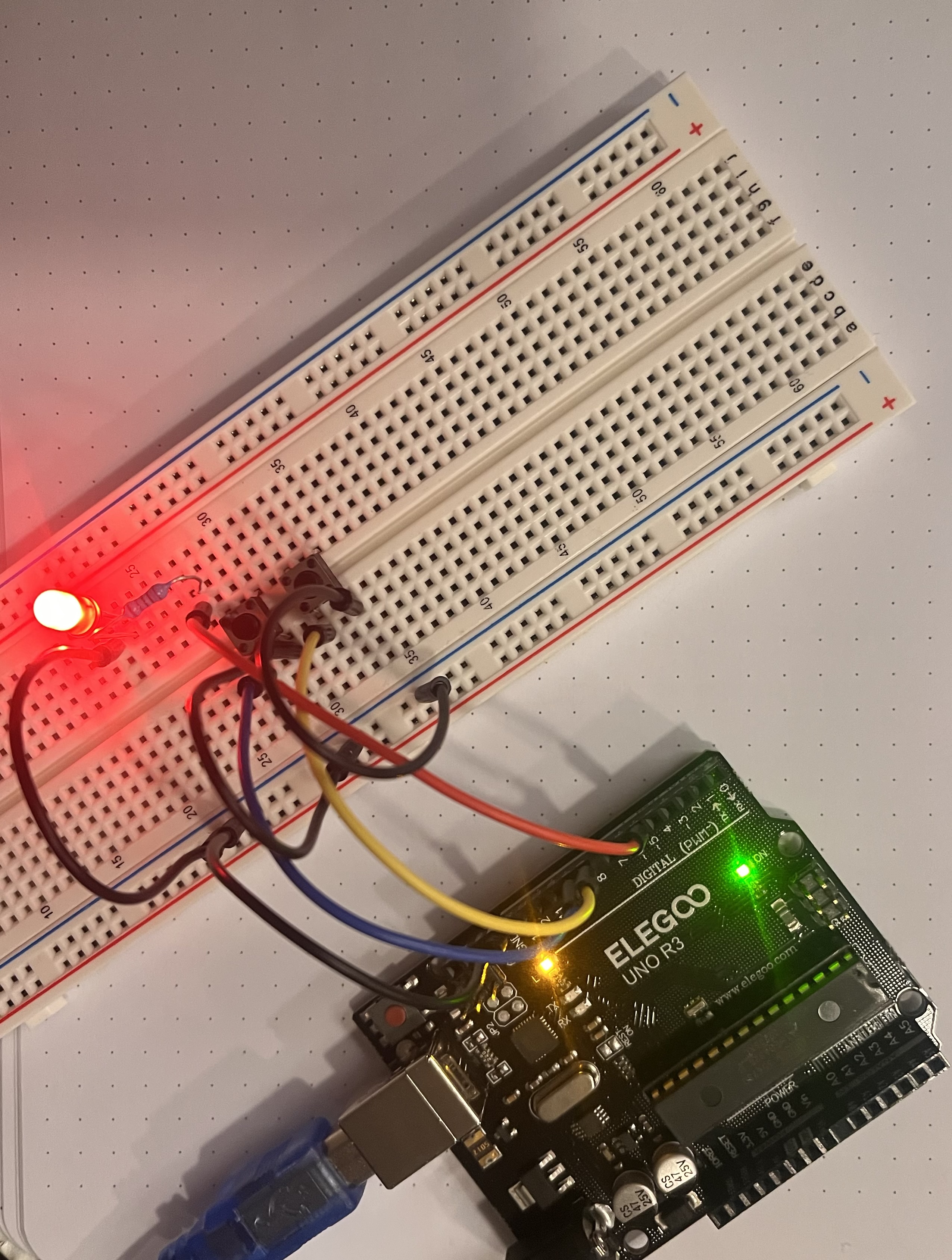
Here is my completed set up on the breadboard:
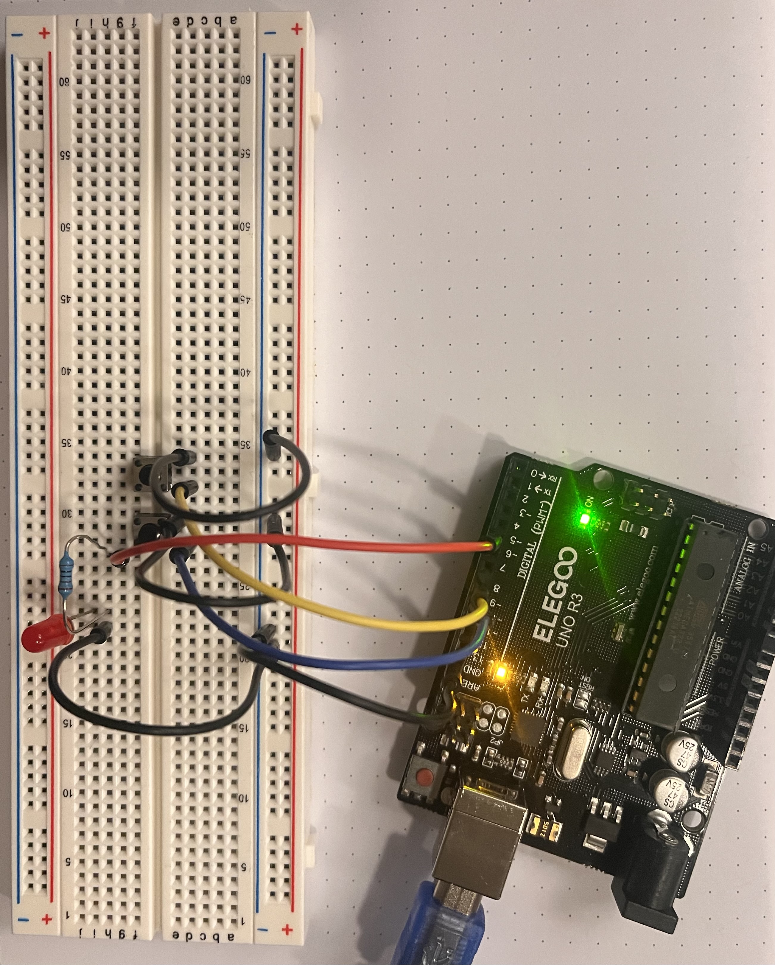
Question: The light turns on when clicking red button on COM3, but switches are not working and controling the light